Display property arrangements
Display property arrangements in ePLAN define how object properties are visually presented in the schematic or graphical editor. They control the position, visibility, formatting, and appearance of property texts associated with symbols, devices, and other objects. They affect only the graphical display, not the technical or logical data of the project.
Display property arrangements are used to:
Standardize the appearance of property texts
Control which properties are visible
Define text positions relative to symbols
Adjust text size, alignment, and formatting
Ensure consistent documentation layout
A display property arrangement determines:
Which properties are shown (e.g. device tag, function text, article number)
The placement of each property (above, below, left, right of the symbol)
Text orientation and alignment
Visibility conditions
Layer assignment
Each symbol or object can be assigned a display property arrangement.
Multiple arrangements can exist for the same symbol type, allowing different visual representations depending on project or company standards.
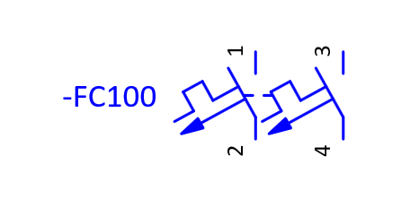
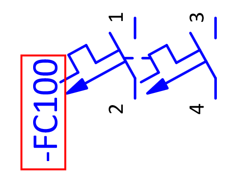
In the example below we have a 2pole circuit breaker symbol that we will use as an example to display how to assign and change display property arrangements.
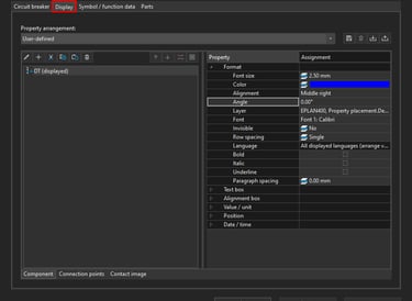
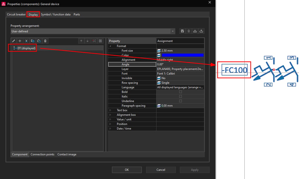
Open the circuit breaker properties by double clicking on the circuit breaker symbol. Then click on the Display tab.
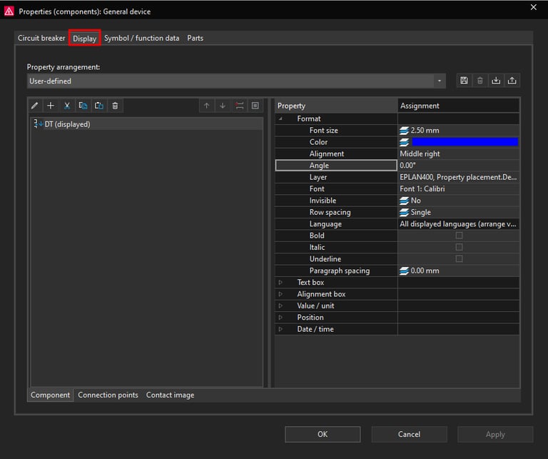
Currently in the Display tab we only have the DT (displayed) property set to be displayed. This is the circuit breaker designation in this case -FC100 which can be seen next to the circuit breaker symbol.
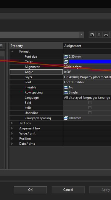
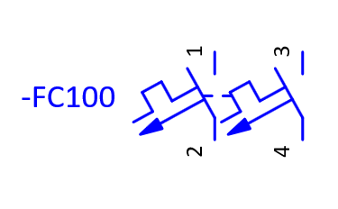
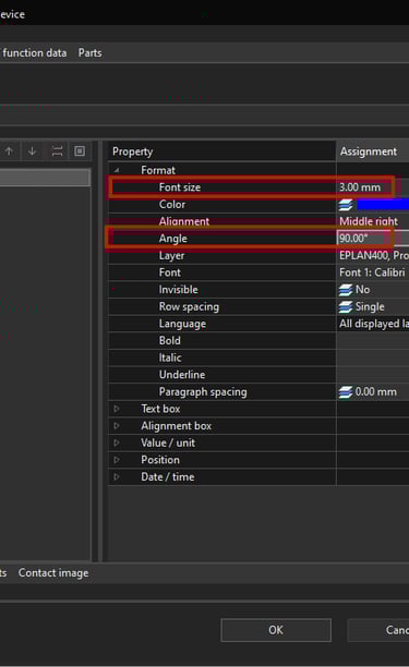
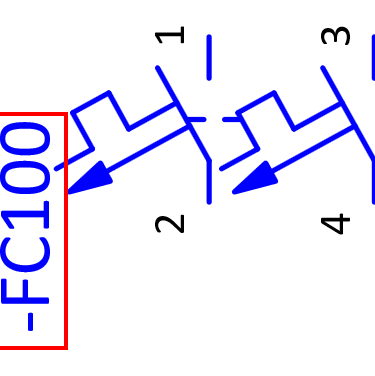
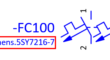
We can use the DT (displayed) property to demonstrate how to change values for properties. For example we can change the font size from 2.50 mm to 3 mm and also we can change the angle in which this property is displayed by changing it from 0.00 ° to 90 °.
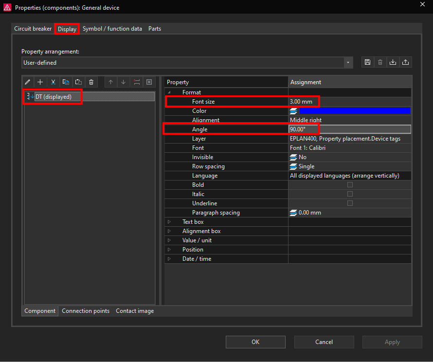
Click on the Apply button to apply the changes and then click om the OK button to close the Properties window. Now notice how the font got bigger and the angle changed to 90 ° for the circuit breaker DT (displayed) property.
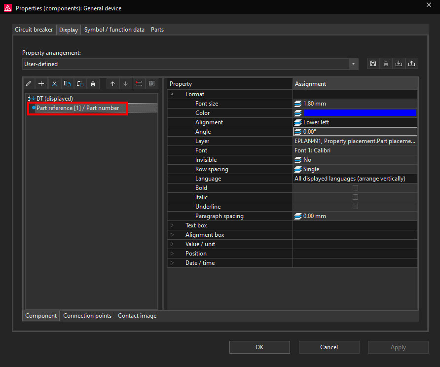
Now we will open the circuit breaker properties window again and go back to the Display tab. We will add the circuit breaker part number to be displayed. To add a new property to be displayed click on the plus icon in the Display tab.
Now we will add the Part number property from the Part reference-Part reference [1] Function. Then we will click on the OK button.
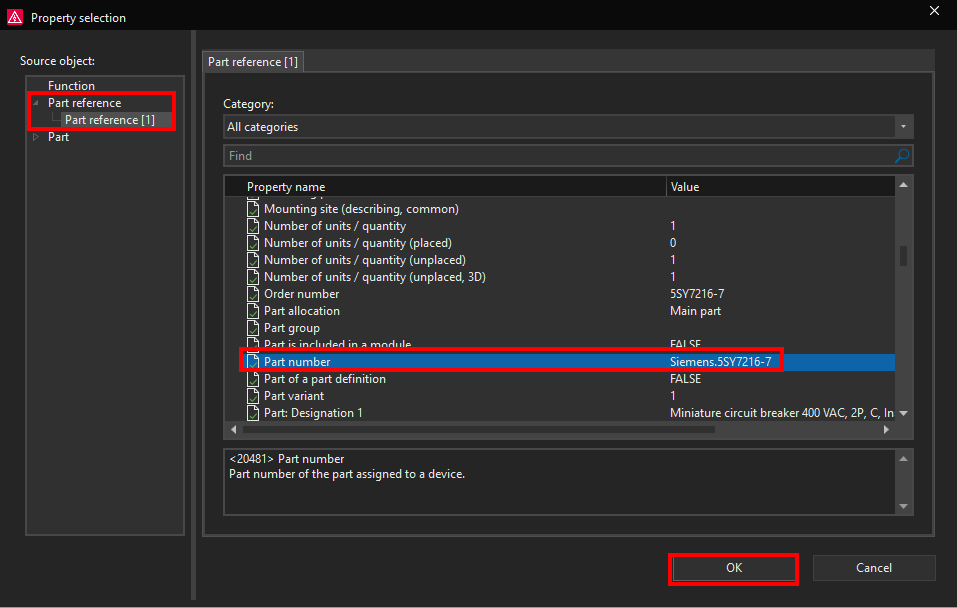
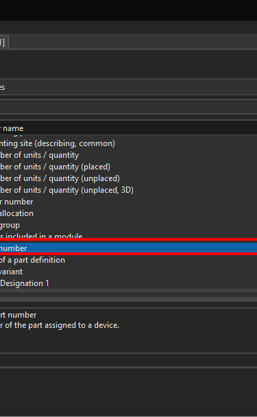
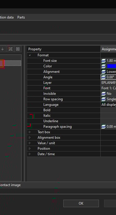
Now the Part reference [1] / Part number property will be visible in the Display tab.
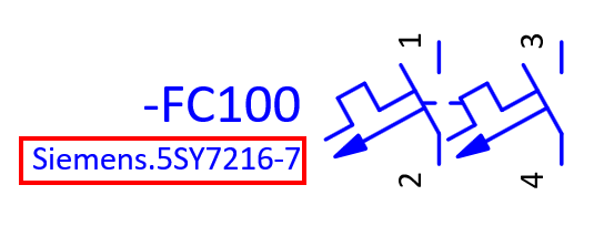
Click on the OK button, the circuit breaker part number will be visible under the DT(displayed) -FC100.
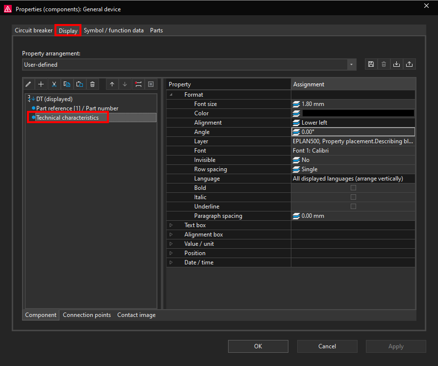
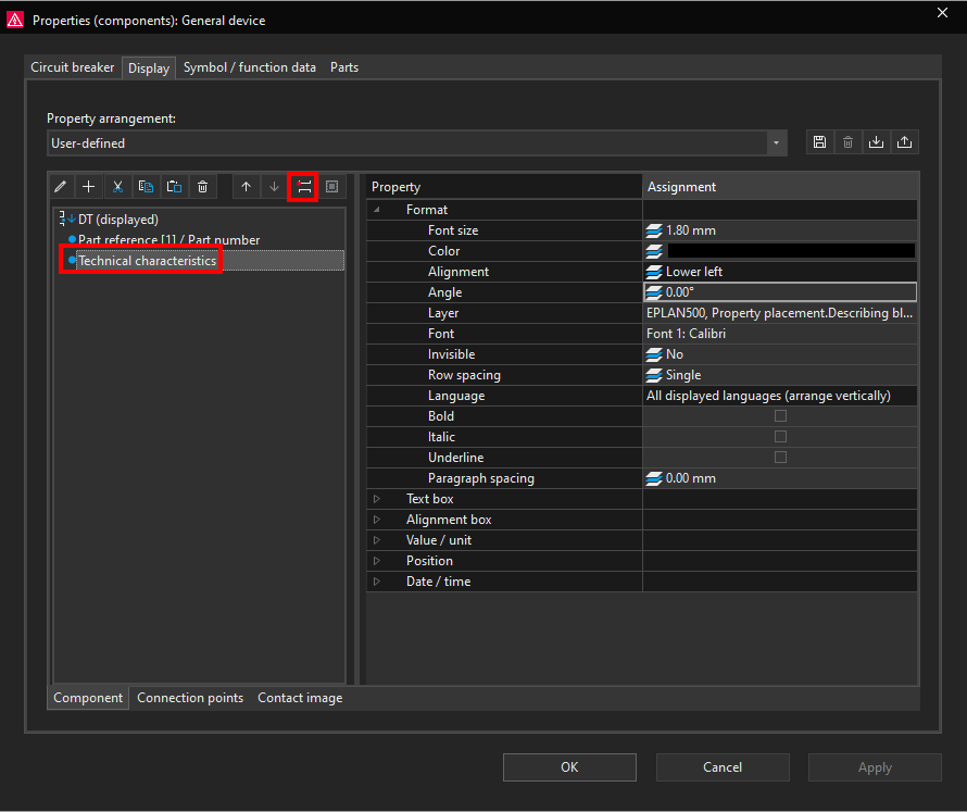
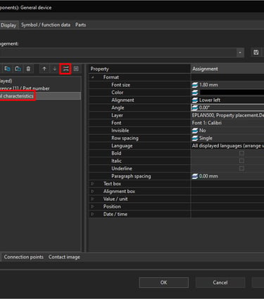
Now in the same way we will add the circuit breaker Technical characteristics property to be displayed under the circuit breaker part number.
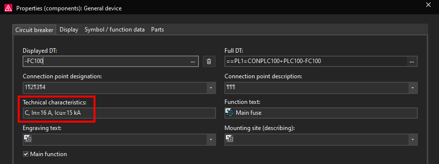
We will go back to the Display tab and we will add the Technical characteristics property to be displayed.
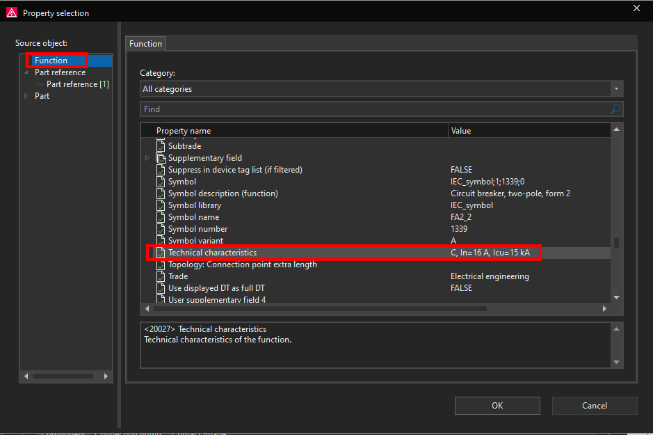
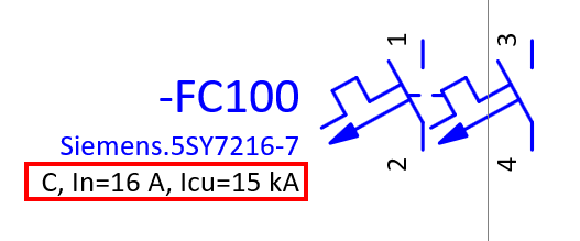
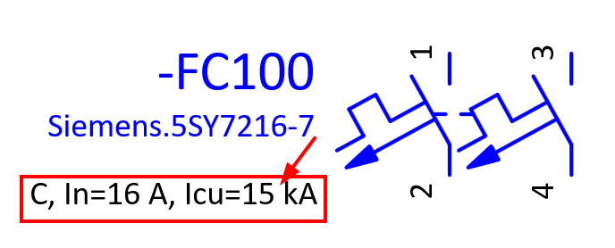
Now the circuit breaker technical characteristics can be seen under the circuit breaker part number.
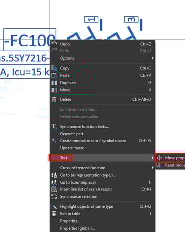
You can also move the position of where the property is displayed by right clicking on the property and then clicking on Text-Move property text.

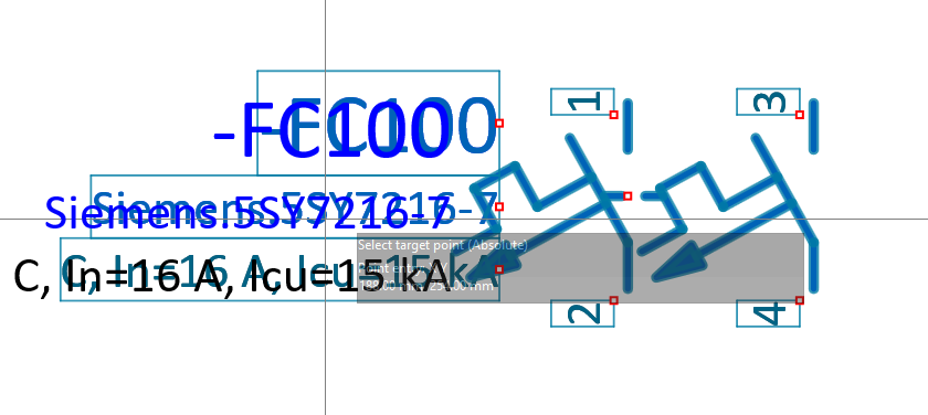
Now click and hold the left mouse button on the property that you wish to move and then by moving the mouse button you can change the property placement position.
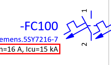
In this case the Part reference [1] / Part number property and the Technical characteristics property are docked to the DT(displayed) property. That means that when you try to move one of these properties you are moving all of the properties which are docked together. In order to move a property that is docked first you have to undock that property in the Display tab. In this example we will undock the Technical characteristics property by selecting it and then clicking on the Undock command.
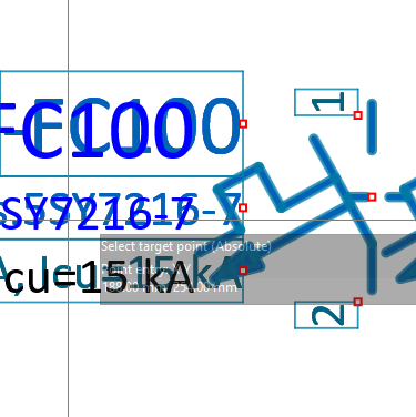
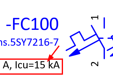
Now we can freely move the Technical characteristics property by using the Text-Move property text command like it was explained above.
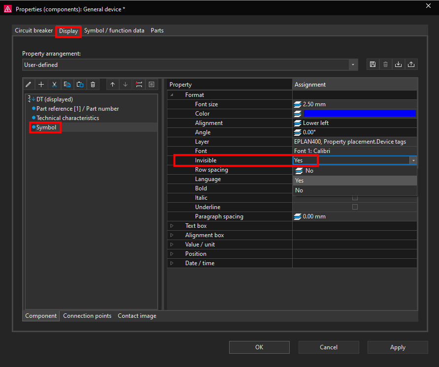
You can also display a property which can be seen while you are working in ePLAN but it is invisible and will not be printed or exported to PDF. To demonstrate this we will add the circuit breaker Symbol name property to be displayed.
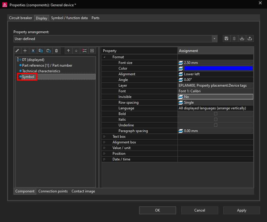
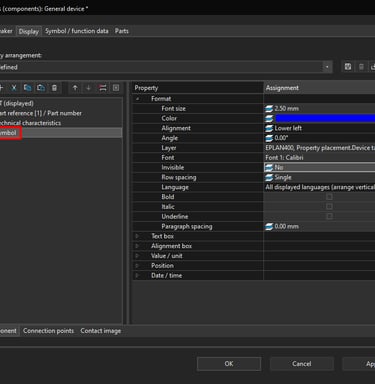
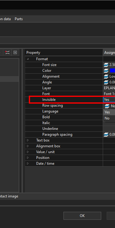
Now we can change the Symbol property Invisible Format from No to Yes.
Now if we click on the View ribbon and then click on the Invisible elements command we can see all of the invisible devices, texts and properties.

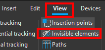
Now we can see the circuit breaker invisible symbol name.

