Wire connection point designations
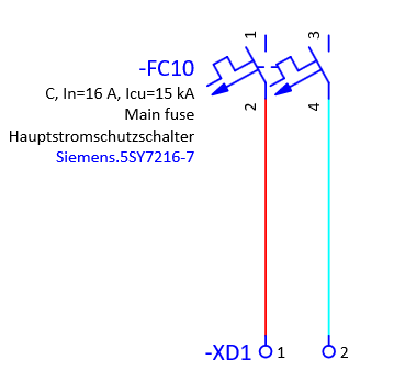
Wire connection point designations define the electrical endpoints of a wire and describe to which connection points of which devices the wire is connected. They are the link between the graphical wire in the schematic and the physical terminals or pins of real components. We will use the connections between a 2 pole circuit breaker and terminals as an example. We will demonstrate how to define the wire connection designation scheme and how to assign wire connection designations according to the predefined scheme.
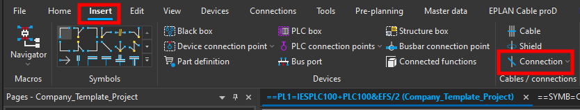
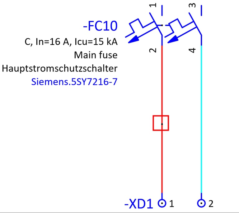
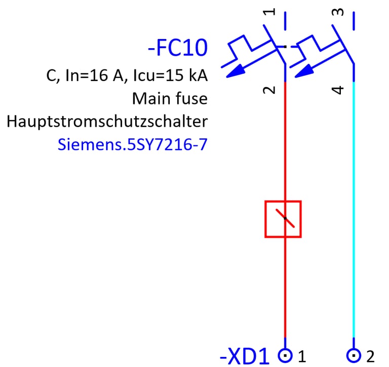
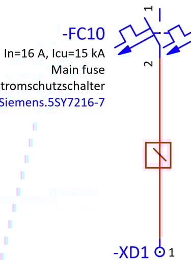
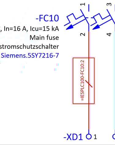
First we will place two connection definition points, one one the connection between -FC10:2 and -XD1:1 and also on the connection between -FC10:4 and -XD1:2. To place a connection definition point click on the Insert ribbon and then click on the Connection definition point command.

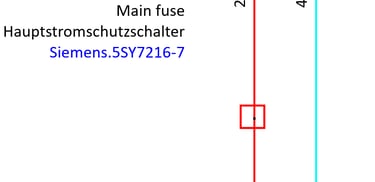
We will place the Connection definition point on the connection between -FC10:2 and -XD1:1. If you cannot see the Connection definition point press the I key on the keyboard.
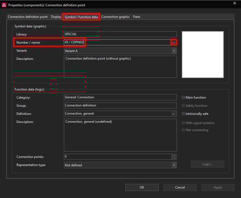
Open the Connection definition point properties by double clicking on it. Here we can change the Connection definition point symbol by going to the Symbol / function data tab and then clicking on the three dots in the Number / name: row.
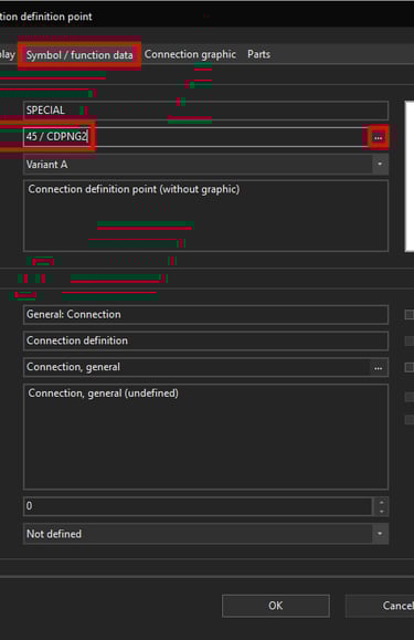
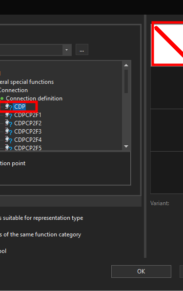
Now we will select the CDP symbol.
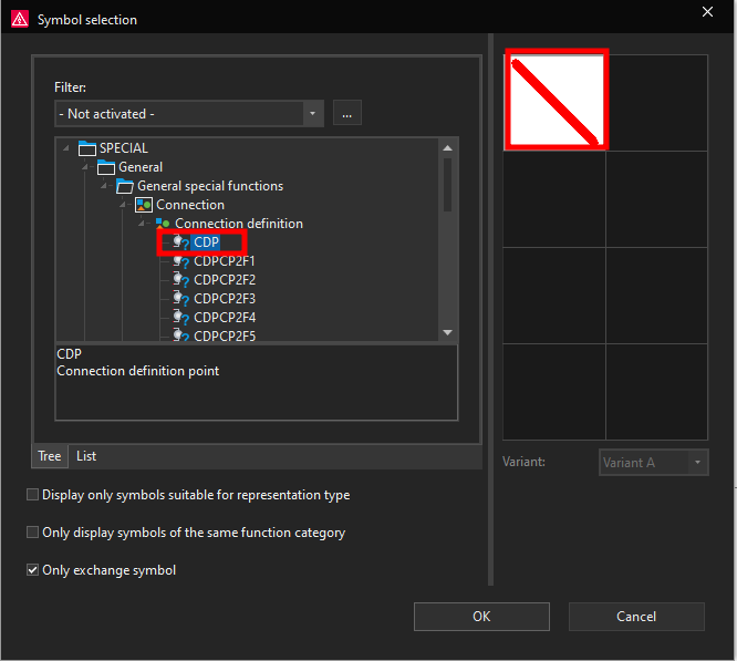
Notice how the Connection designation symbol changed.
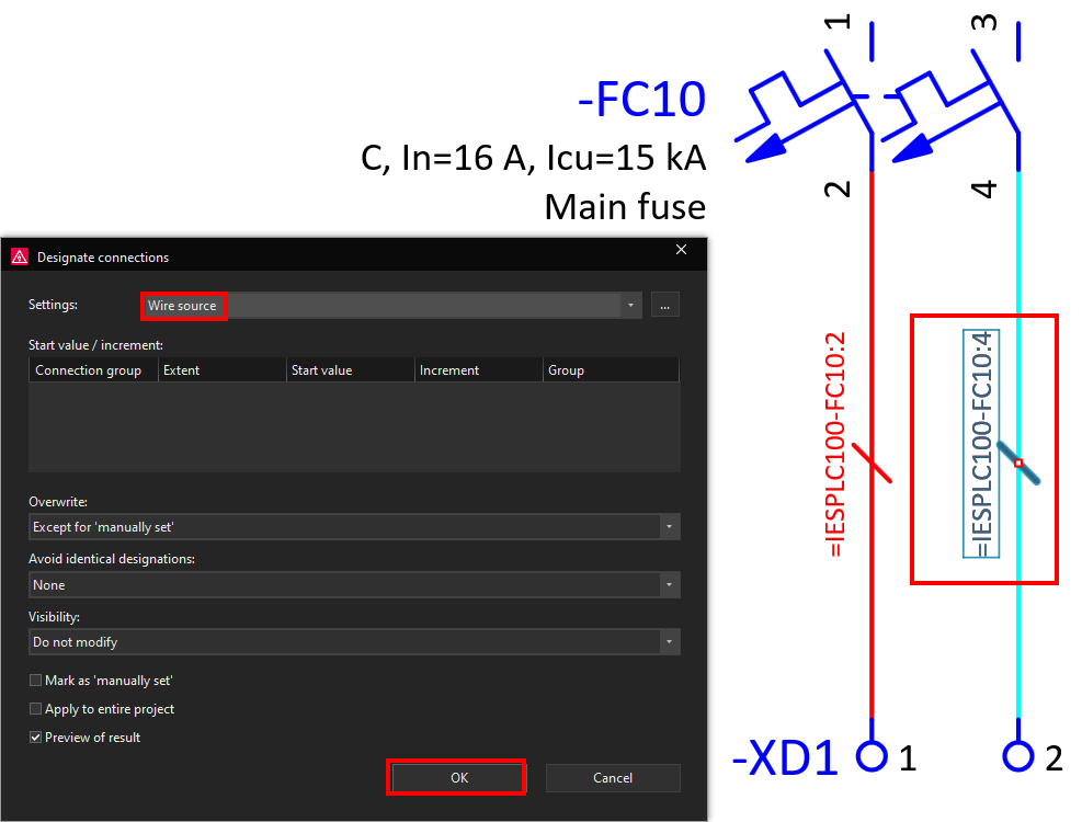
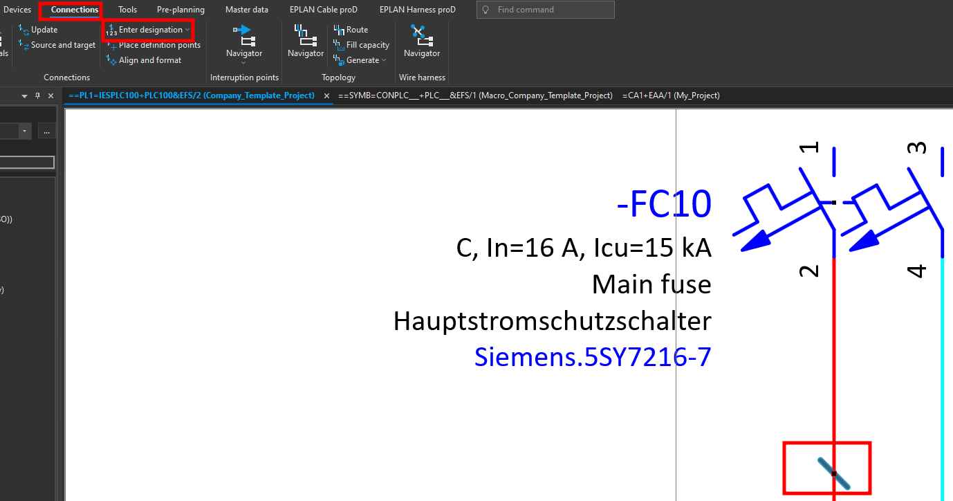
Now we will start creating the wire designation scheme. Click on the Connection point designation that was inserted previously and then click on the Connections ribbon and then click on the Enter designation command.
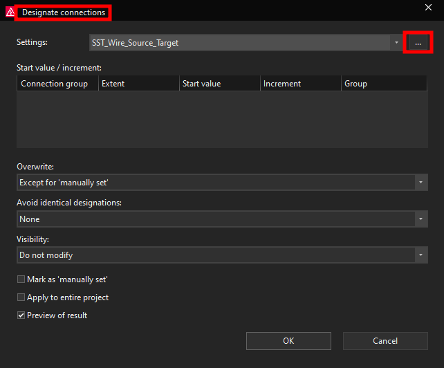
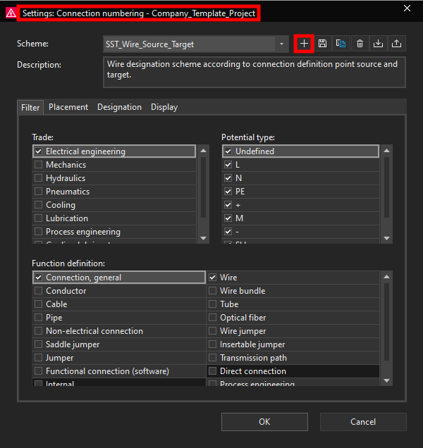
Now the Designate connections window will open. Here it is possible to select one of the already created schemes for creating connection designations, however we will demonstrate how to create a new connection designation scheme. To start creating a new connection designation scheme click on the three dots in the top right corner.
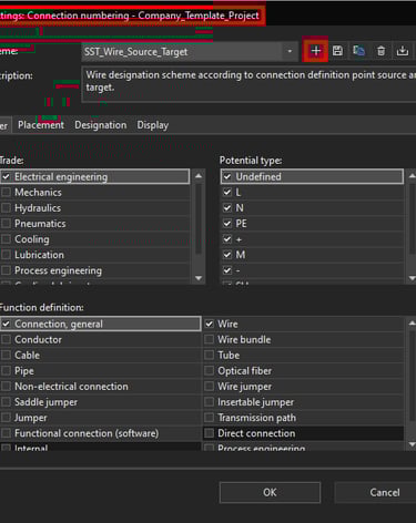
Now the Settings: Connection numbering window will open. Here we can start creating a new connection designation scheme by clicking on the plus icon at the top right.
Now the new scheme window will open, here we can give the new scheme a name in this case we will give the new scheme the Wire_Source name since we will be using this scheme to designate wires according to the connected source device and device connection points.
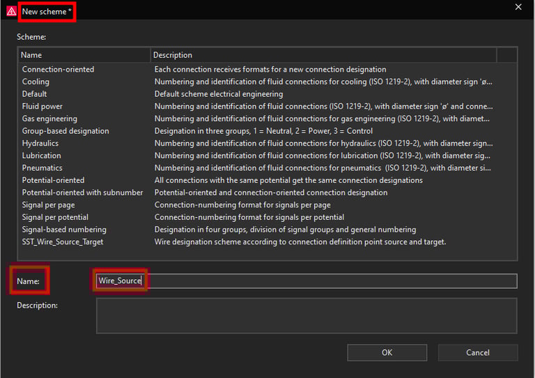
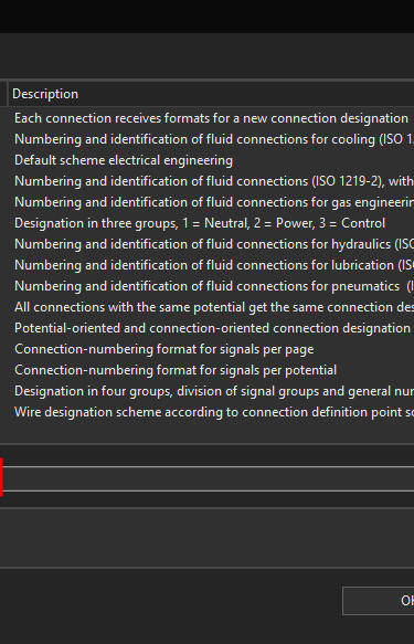
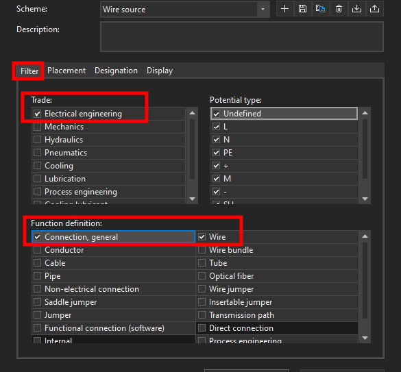
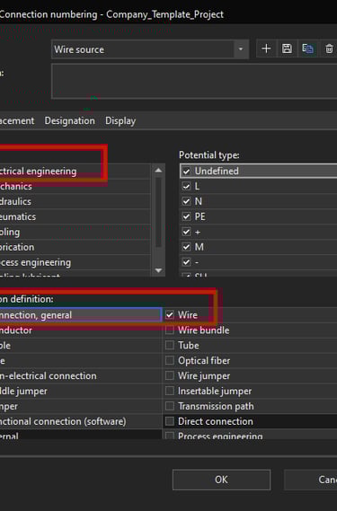
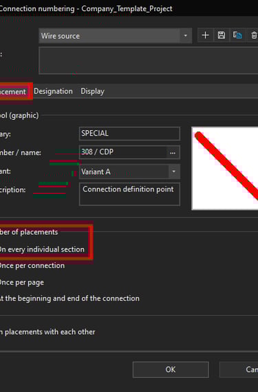
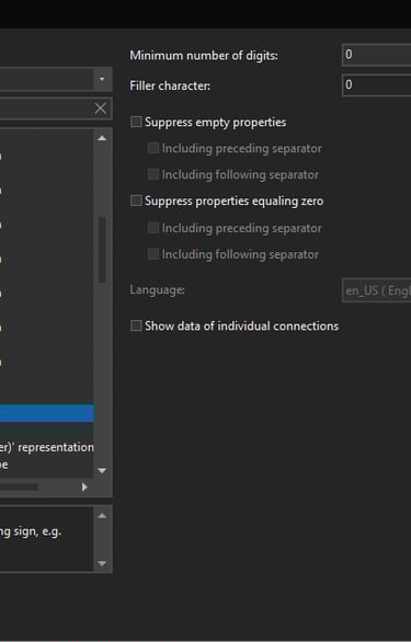
You can also give the scheme a description, once you are finished click on the OK button. You can now see the name of the new scheme at the top. While we are here in the Filter tab we will select only Electrical engineering in the Trade and we will select only Connection, general wire in the Function definition.
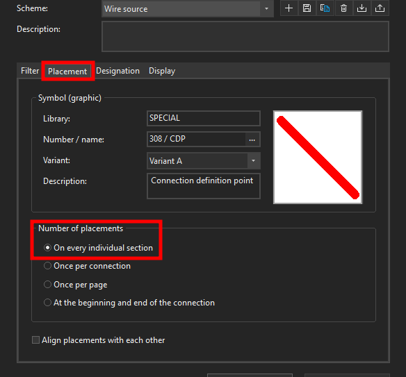
In the Placement tab we will select the option to place wire designations On every individual section in the Number of placements options.
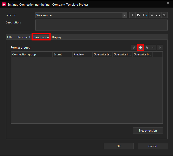
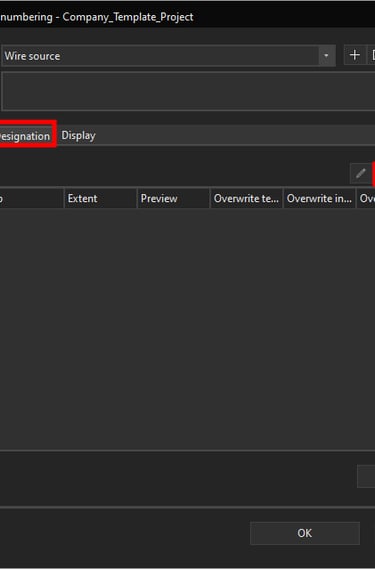
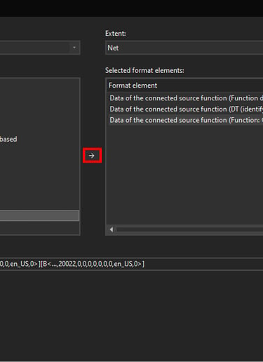
Now we will switch over to the Designation tab. Here we will actually define the format for the wire connection designation according to the wire source connections. To start defining a wire connection designation format click on the plus icon on the top right.
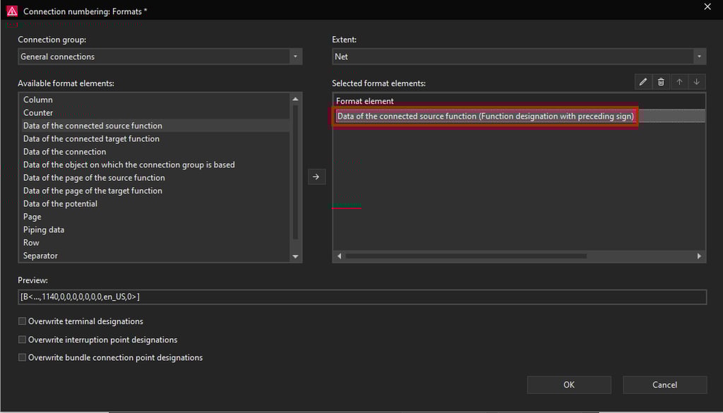
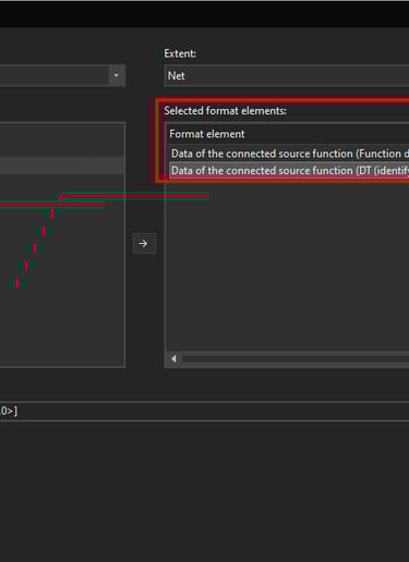
Now the Connection numbering: Formats window will open. Since we are creating a scheme according to the wire source connections we will select the Data of the connected source function format element and then click on the arrow in the middle that is pointing to the right.
Now we will select the Function designation with preceding sign property and then click on the OK button.
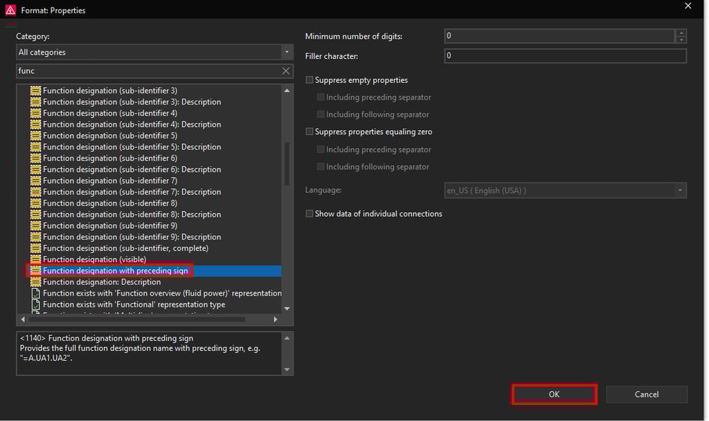
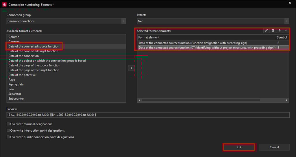
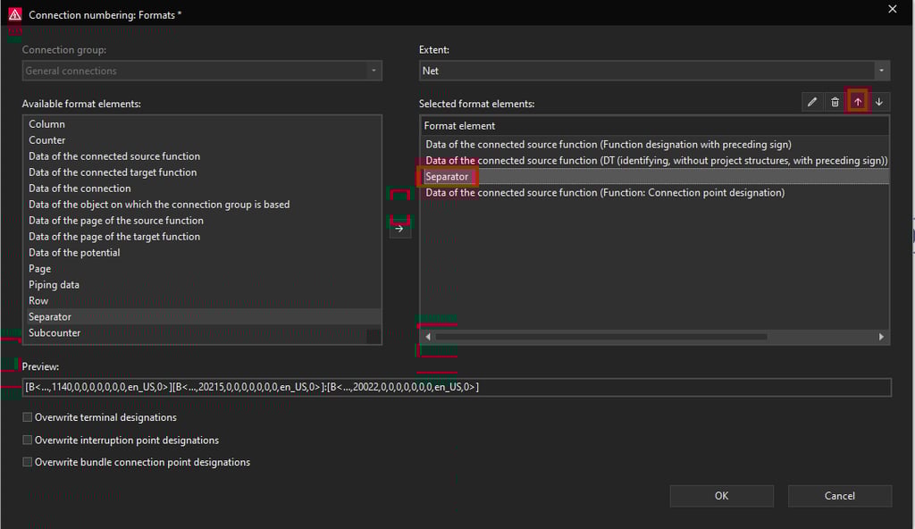
Now we have added the function designation and the DT of the source device however to complete this wire source wire designation scheme we will also add the device connection point designation format element from the Data of the connected source function.
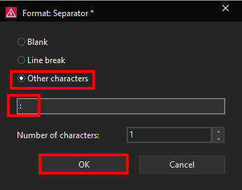
As a final “touch” we will also add the Separator element with the : character to separate the connection point designation from the device designation. Once we add the separator character we will have a wire designation scheme like this =Function designation-DT:connection point designation. To add the Separator character select the Separator on the left side and then click on the arrow in the middle that is pointing to the right.
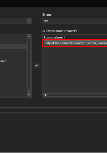
Now the added format element in this case the Function designation with preceding sign will be visible under the Selected format elements on the right side.
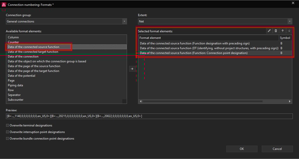
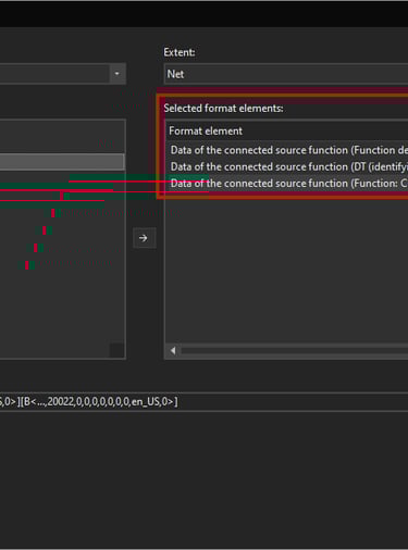
Now in the same way we will add another format within the Data of the connected source function format element this time we will add the Data of the connected source function (DT (identifying, without project structures, with preceding sign)).
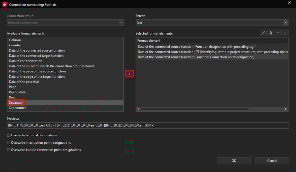
Now the Format Separator window will open, here we will add the : character to be displayed.

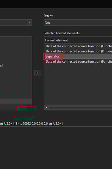
by using the arrow key that points up move the Separator character one position up.
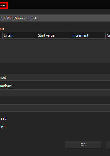
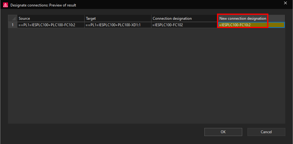
Now we are finished with creating the wire source connection designation scheme. Click on the OK button in other windows until you get to the Designate connections: Preview of result window.
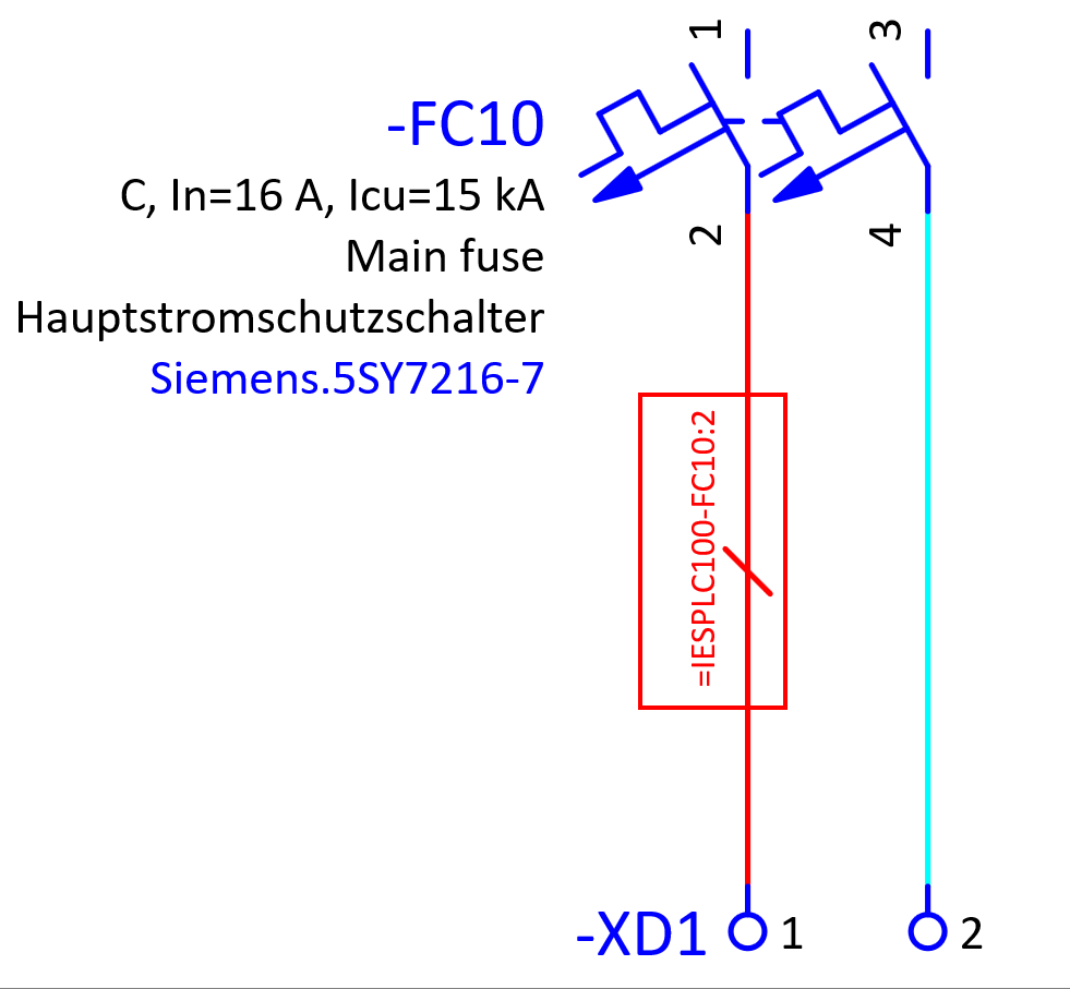
Now we can copy this connection point designation and place it on the other connection between the -FC10:4 and -XD1:2. By selecting the copied connection point designation and clicking on the Enter designation command in the Connections ribbon we can assign the wire source connection designation by using the wire source scheme we created earlier.